Liquid to Liquid Heat Interchanger: The basic construction and working of any heat transfer equipment more or less remain the same. Only a few modifications are included…
Construction of the Liquid to Liquid Heat Interchanger
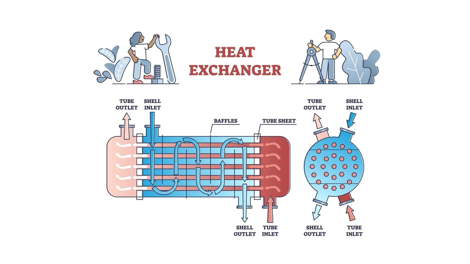
The construction of a liquid-to-liquid heat interchanger is shown in Figure 1.1. Normally, tube sheets, spacer rods, and baffles are assembled first and then tubes are installed. The most important parts in the construction of the heat interchanger are the baffles.
The appropriate size of tube sheets is chosen for the fabrication. One or more guide rods are fixed to the tube sheets by means of set screws. Baffles consist of circular discs of a metal sheet, with one side cut away. Baffles are placed at appropriate places using guide rods. The baffles are with appropriate spacing using short sections of the same tubing as shown in Figure 1.1. Baffles have perforations through which tubes are inserted. The ends of the tubes are expanded into the tube sheets. The above assembly is enclosed in a shell.
The shell has a provision for introducing the heating medium, hot fluid. The outlet for the fluid is at the right-side top. On each side of the tubes, two distribution chambers are provided. The left-side chamber contains an inlet for fluid to be heated. The outlet for the hot fluid (that is heated) is provided at the center of the right-side distribution chamber.
Working
The hot fluid (heating medium) is pumped from the left side top of the shell. The fluid flows outside the tubes and moves down directly to the bottom. Then, it changes its direction and rises again. This process is continued till it leaves the heater. Baffles increase the velocity of the liquid outside the tubes. Baffles also allow the fluid to flow more or less at right angles to the tube, which creates more turbulence. These help in reducing the resistance to heat transfer outside the tubes. Baffles lengthen the path and decrease the cross-section of the path of the cold fluid. The path of travel is shown in Figure 1.1. The baffles get heated and provide a greater surface area for heat transfer. Simultaneously, during the flow, the tubes also get heated. As a result, the film coefficient inside the tube also increases.
The liquid to be heated is pumped through the inlet provided on the left side distribution chamber. The liquid passes through the tubes and gets heated. The flow of liquid is single-pass. The heated liquid is collected from the right-hand side distribution chamber.
Advantages of Liquid to Liquid Heat Interchanger
In a liquid-to-liquid interchanger, heat transfer is rapid as the liquid:
- passes at high velocity outside the tubes.
- flows more or less at right angles to the tubes.
Make sure you also check our other amazing Article on : Floating Head Two Pass Heater