
Aim: Description of construction, working, and application of pharmaceutical machinery.
Table of Contents
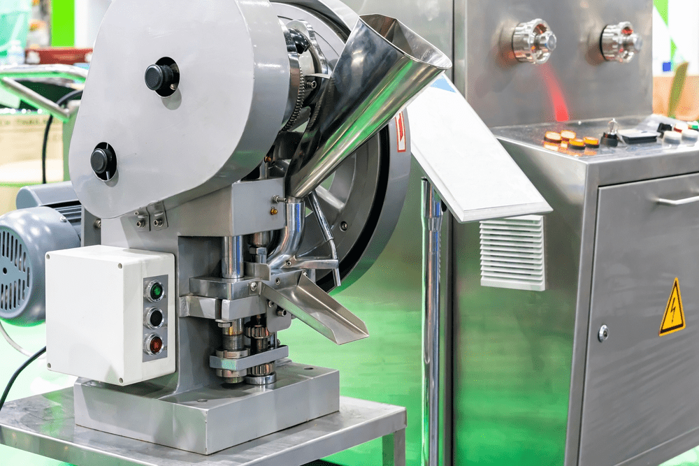
Tablet Compression Machine
Tablets are formed by compressing the granules using the compression machine. Tablet formed in compression machine by pressing the granules in die with a lower and upper punch. Tablet formation takes place by the combined pressing action of two punches (lower and upper) and a die. Now it is possible to produce more than 500,000 tablets per hour due to different innovations in tablet compression machines.
Principle of Tablet Compression Machine:
In the tablet compression machine main principle is compressing the upper and lower punch in a die hole, the hydraulic pressure plays a key role. This pressure is transmitted unreduced through the static fluid. Any externally applied pressure is transmitted via the static fluid to all directions in the same proportion. It also makes sit possible to multiply the force as needed. If we increase the hydraulic pressure more compressing force on the tablet then it becomes harder.
Different Stages of Tablet compression process:
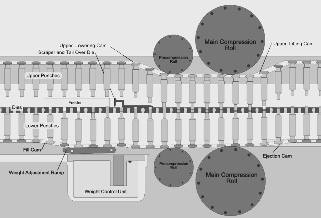
The tablet compression process is divided into four distinct stages. These stages include filling, metering, compressing, and ejection.
Tablet Compressing Stage
Filling: Formulation is overfilled at the compressing station
Metering: Overfill is removed
Compression: Tablet is formed by the pressure of punches within die
The ejection: Tablet is ejected from the die
Filling:
The filling stage of the tablet compression process involves the transfer of raw materials into position for tablet compression. These raw materials have undergone prior processing by wet granulation, dry granulation (roller compaction), sizing, or other processes. The final formulation is then blended to yield a homogeneous blend. The blend then flows to the compressing machine punch-die cavity. The punch die cavity is composed of a punch die and a lower punch. The position of the lower punch within the die determines the volume of the punch-die cavity. This volume must be appropriately sized for the weight of granulation to be compressed into tablets. The granulation is overfilled on the die table (turret) to ensure complete filling of the punch-die cavity volume.
Metering:
The metering stage of the tablet compressing process involves the removal of excess granulation from the compressing machine. This stage enables the exact weight (volume) of granulation to be compressed into tablets. The exact weight of granulation is controlled by the height of the lower punch in the die. The height of the lower punch is controlled by the metering cam (also called the dosage cam). The lower punch is raised to the appropriate level in the die to provide the exact weight of granulation in the punch-die cavity. The excess granulation is scraped from the surface of the die table. The metering stage is similar to the method used to measure flour when baking a cake. A measuring cup is first over-filled with flour; then a knife is used to scrape off the excess. The exact amount of flour is then legged in the measuring cup.
Compression:
The compression stage of the tablet compressing process forms the tablet. This stage involves bringing together the upper and lower punches under pressure within the die to form the tablet. As the punches enter the compressing stage, the upper and lower punches move between two large wheels called pressure rolls. These pressure rolls push the punches together to form the tablet. The distance between the upper and lower punches determines the thickness and hardness of the tablet. When the punches are close together, a thin and hard tablet is created. When the punches are farther apart, the tablet made is so Ger and thicker. The proper balance of thickness and hardness determines the optimum roll distance for any specific product. These adjustments are made while keeping the tablet weight constant.
Ejection:
The ejection stage of the tablet compressing process involves the removal of the tablet from the lower punch-die station. In this stage, the upper punch retracts from the die cavity and rises above the turret table. Then the lower punch rises in the die, which in turn pushes the tablet upward to the top surface of the die table and out of the die cavity. A scraper (also called take-off scraper or tablet rake-off) then pushes the tablet off the die table away from the compressing machine into the collection container.
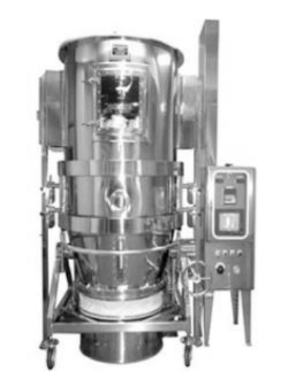
Fluidized bed dryer
Drying is very much important for wet granules for compression into the tablet and for modifying the characteristics of viscous and sticky materials. Drying is commonly the last step in the unit process before compression into tablet form and packaging.
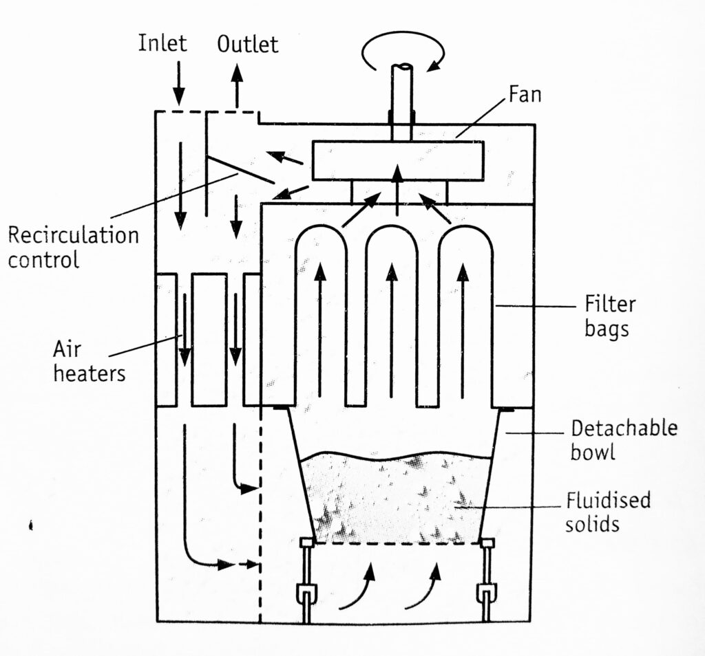
Principle: Fluidized bed dryer is better known by name because hot air (gas) or ambient air is allowed to flow upward at high pressure through a perforated bottom of a vessel containing a bed of particulate solids. At the same time, the solution of adhesive is sprayed into the container. It makes the particles become granulating that contain adhesive. Being unceasingly dry through hot air, the moisture in the granulating is evaporated. The process is carried out continuously. Finally, it forms ideal, uniform, and porous granules.
The velocity of hot air is more than the settling velocity of the granules/particles by which they remain suspended in a stream of hot air. This condition is called a fluidized state. The hot air surrounds every granule/particle and completely dries them.
Construction: Two types of FBD are available, vertical and horizontal which are made up of stainless steel or plastic. Vertical type is used for batch drying and horizontal is used for continuous drying. A detachable vessel is placed at the bottom of the dryer for the loading and unloading of material. This vessel has perforated mesh through which hot air with high pressure is passed. Bag filters are placed above the vessel for the collection of dried material.
Bag Filters: These are placed above the drying vessel for the recovery of particles and dried material. Various features of these filter bags are:
- These are made of different types of material or fabrics- cotton, nylon, polyester, satin, and polypropylene.
- These can bear high pressure of hot air or high flowrates
- Durable construction
- Good resistance to wear and abrasion
- These are available in different pore sizes, thicknesses, fabrics, and permeability.
- Anti-static fabrics are also available.
- These are available in different sizes which can easily fit in equipment.
Working: The material to be dried is placed in a detachable vessel at bottom of the dryer. The air is introduced from below through the prefilter, which is heated by means of heaters installed therein. Simultaneously fan is also allowed to work. As the velocity of air is increased, the bed begins to expand, and further increase causes turbulent motion of particles called fluidization. The granules/particles remain suspended in the air stream. Later on, a state of pressure is reached at which frictional drag on the granules/particles is equal to the force of gravity. The particles rise instream of the air due to the high velocity of the gas, this condition is called a fluidized state.
ASSEMBLING:
- Unclamp the fixing bolts of retarding chamber and allow it to rest on the trolley. Take out the trolley along with the retarding chamber.
- Check and certify the suitability of the clean finger bag.
- Fix the loops of the finger to the hooks of the shaker.
- Place the bag in between the retarding chamber and the fluidization chamber.
- Clamp the retarding chamber on the body with fixing bolts.
OPERATION:
Loading
- Load the bowl with the material to be dried.
- Take the product uniformly in the bowl to avoid lumps.
- Move the product bowl below the retarding chamber keeping the window in the viewing position.
- Position the bowl.
- LiG the bottom of the FBD by moving the jack handle to the opposite side and sealing the trolley to the retarding chamber
- Check and ensure that there is no leakage.
- Set the timer and switch on heating and fluidization, maintaining the desired inlet air temperature.
- Stop drying at intervals specified in BMR and dedust the finger bag by shaking it.
- Take out the trolley and rake the granules to avoid the formation of lumps.
- Watch the fluidized flow through the Perspex windows.
- Continue heating till the required outlet air temperature is achieved. Air-dry if mentioned in BMR
- Put off the heaters and bring the timer to zero.
Unloading
- Ager drying is complete put off them an in switch
- Shake the finger bag vigorously and dust retarding the chamber.
- Unlock and draw the bowl.
Advantages Of Fluidized Bed Dryer:
- Thermal efficiency is 2-8 times that of tray drier
- It is available in different sizes having a drying capacity in the range of 5-250 kg/hour.
- Free-flowing granules/particles are made.
- It can also be used for mixing material with high efficiency.
- It can be used for both batch and continuous drying.
- Loading and unloading of material is very easy due to the detachable vessel
- Higher drying temperatures than tray and truck dryer.
Wipe out the body of the FBD retarding chamber, trolley& bowl by using a clean dry lint-free duster. Further dry by running FBD at 70°C (without material)for 15 minutes.
Fluidized Bed Coater
Or
Wurster Coater‐ Pellet Coater Fluidized Bed Spray Coating
Principle: An alternative approach to pan coatings that provides the mixing and drying characteristics required by the film coating process is to use fluid bed technology. Fluid bed technology helps in achieving fast and uniform coating using air to mix, coat, and dry the substrate at the same time. This technology originated from fluid bed dryers used for wet powder material drying operations. Fluid bed equipment was modified to coat tablets as an alternative innovation. With the help of spray nozzles granulating liquid or coating solution is sprayed to produce granules or coating of particles respectively and then dried with hot air. The particles are lined from the bottom and suspended in the air stream. This condition is called a fluidized state. A fluidized bed is a bed of solid particles through which hot air is passed at high pressure through the air distribution plate/bottom of the container.
Construction and working
Fluid bed coating equipment later became popular for coating multi-particulate systems such as beads and nonpareil seeds. The figure below shows a diagrammatic representation of the fluid bed coating process by a bottom spray method which is widely used to film coat multi particulate systems.
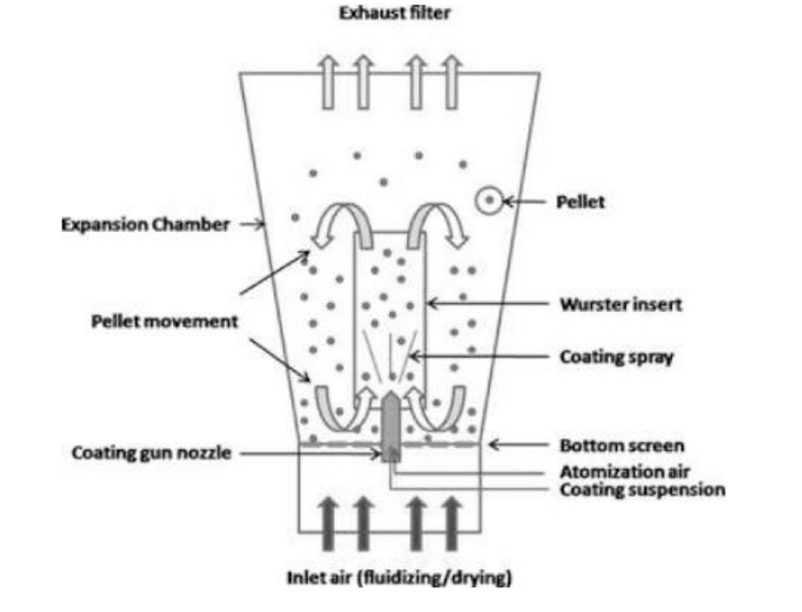
Bottom spray fluid bed Coating (Wurster Coating)
- The drying inlet air is passed upwards through the bottom perforated plate into the fluid bed chamber.
- This air passes inside and outside of the central cylinder (Würster column), which houses a spray gun perpendicular to the bottom plate and parallel to the Würster column.
- The air is taken out of the equipment from the exhaust filters mounted on the top of the equipment.
- The material to be coated is loaded in the fluid bed chamber and fluidized.
- The inlet air is maintained at a certain velocity and temperature to help in both fluidizations of the material as well as its drying during the coating operation.
- The height of the Würster column is adjusted such that pellets above the bottom plate (referred to as the Down-bed) are pulled in the Würster column due to the Venturi effect and pass through the liquid spray of coating solution from the spray gun positioned parallel to the column within.
- When the material being coated reaches the expansion chamber (referred to as the Up-bed), its velocity drops and it falls by gravity around the Würster column and is then recycled back to the coating zone by the Venturi effect.
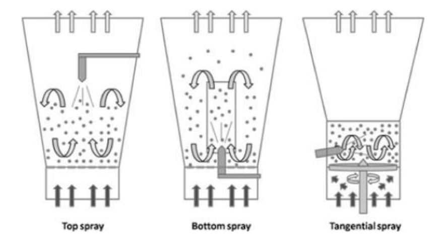
Examples of Fluid Bed Technology Processes Include:
Wurster Process (Bottom Spray)
- The most commonly used type of fluid bed process for multi-particulate coating.
- In this process, there is a concurrent (same direction) movement of powder particles or pellets and liquid spray.
- The coating process occurs within the Würster column.
Granulator Process (Top spray)
- The most commonly used type of fluid bed process for granulation.
- In this process, there is a counter-current (opposite direction) movement of powder particles or pellets and liquid spray.
Rotor Process (Tangential spray)
- Originally designed for the preparation of granulates (pellets), this process has also become adapted for the film coating of multi-particulates.
- In this process, the powder particles or pellets move in a helical fashion due to the spinning rotor disk on the bottom of the equipment. The liquid is sprayed within the moving powder or pellets.
The existence of these three processing concepts has resulted in the major suppliers of fluid bed equipment offering all three as standard inserts for a basic fluid bed processing unit.
Application & process:
- Pellets and Granules coating and drying of particulate materials.
- It is ideal for heat-sensitive and non-heat-sensitive products in Pharmaceuticals, Biotech, Nutraceuticals, Cosmetic, Chemicals, Biochemical, Food, Dairy, Confectionery, Agrochemical, Herbals, Ceramics, Detergents, and Pharmaceuticals Institutes.
The equipment is used in the application for the following process.
- Aqueous or Solvent based solutions or suspensions
- Enteric Release coatings
- Controlled release coatings.
- Fine particle coatings
- Active layering.
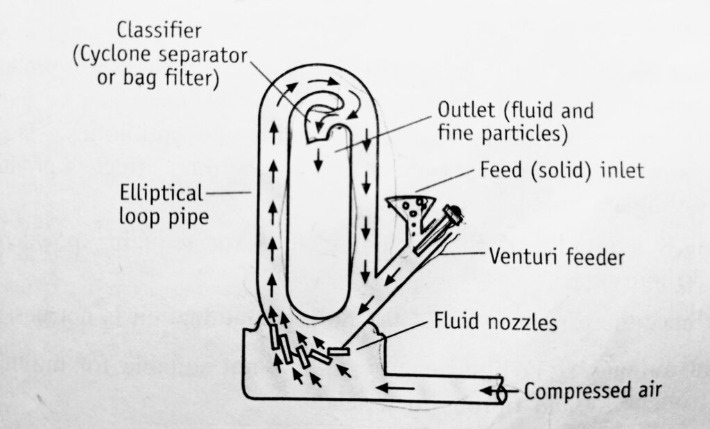
Fluidized Energy mill
A Fluidized Energy mill, also known as micronized, or jet mill is a type of mill that consist of a hollow toroid that has a diameter of 20-200mm depending on the height of the loop which can be up to 2m. A size-reduction unit depending on its action on collisions between the particles being ground, the energy being supplied by a compressed fluid, (e.g., air or steam) that enters the grinding chamber at high speed. Such mills will give a product of 5 mu m or less they have been used for the fine grinding. Interparticle attrition that happens inside the tube of a fluid energy mill is the principle of size reduction. It operates by particle impaction and attrition. A fluid or milling gas, usually air or inert gas is injected as a high-pressure jet through nozzles at the bottom of the loop. The powder particles in the mill are accelerated to high velocity. The kinetic energy of the air plus the turbulence created causes inter-particle (particle-particle collision) and particle-wall contact resulting in particle size between 2 and 10 micrometers. The fluidized effect transports the particles to a classification zone where the size classifier retains the particles until sufficiently fine to be removed.
The particle size and share are determined by;
- The speed of air/inert gas
- Feed rate and size
- The configuration of the mill
- Design of the classifier
- The position of the nozzle
- The impact between the feed and air
Construction:
It consists of a loop of pipe, which has a diameter of 20 to 200mm, depending on the overall height of the loop, which may be up to about 2 m. There is an inlet for the feed and a series of nozzles for the inlet of air or inert gas. It also has an outlet with a classifier which allows the air to escape but prevents the particles to pass until they become sufficiently fine.
The Fluid Energy Process:
Fluid Energy Mills are compact, versatile machines used for a number of operations such as size reduction, drying, blending, coating, and chemical reactions involving at least one solid material. Fluid Energy Mills eliminates the limitations of conventional grinding machines. In Fluid Energy Mill there are no moving parts and no grinding media. A source of compressed air or gas or high-pressure superheated steam is used to run the Mill.
Working:
The air or inert gas is introduced with very high pressure through the nozzles. Solids are introduced into air steam through the inlet .due to a high degree of turbulence, impact, and traditional forces that occurs between the particles. The fine particles are collected through a classifier. The fluid energy mill reduces the particles to 1 to 20 microns. To get a very fine powder, even up to five microns, the material is pre-treated to reduce the particle size to the order of 100 mesh and then passed through a fluid energy mill.
Pharmaceutical uses of fluidized energy mill
- Fluidized energy is used in milling thermolabile materials
- It is the choice of the mill when a higher degree of drug purity is required
- A fluidized energy mill is used for the fine grinding of frits, Kaolin, Zircon, titanium and calcium, and alumina.
Advantages of Fluidized Energy Mill
- The machine has no moving parts and thus the tendency of contamination due to the wear of parts is minimized.
- The equipment is easily sterilized.
- Small particle size (between 2 and 10) is usually obtained at the end of milling.
- Thermolabile materials/heat-sensitive substances such as sulphonamides, vitamins, and antibiotics, can be milled with little degradation since the heat produced by the process is nullified by the cooling effect of the expansion of the compressed gas.
Disadvantages of Fluidized Energy mill
- The tendency of forming aggregates or agglomerates ager milling.
- Generation of amorphous content due to high energy impact.
- Formation of ultra-fine particles
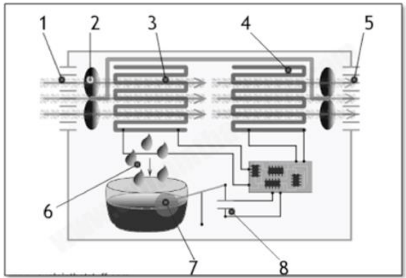
Dehumidifier
Principle‐ A dehumidifier is a bit like a vacuum cleaner: it sucks in air from your room at one end, takes the moisture out of it, and then blows it back out into the room again. The moisture drips through into a collection tank that you have to empty, from time to time. How is the moisture removed? That is where a dehumidifier is more like an air conditioning unit(sometimes called an air-con or HVAC, which stands for heating ventilating air conditioning unit), which, itself, works a bit like a refrigerator.
The compressor cooling system is the most important part of condensation dehumidifiers. It allows for condensing the steam and lowering water contents in the air. At the heart of the cooling system lies a compressor that compresses and pumps the refrigerant, forcing it to circulate around the whole system. The higher the pressure gets, the more the temperature grows. A compressed refrigerant (in a gaseous state) is transferred by a pipe to the condenser, where it is cooled down. The heat of the refrigerant is received by the air around the exchanger (condenser). The refrigerant changes its state from gas to liquid due to its pressure and temperature drop. A condensed refrigerant runs through the de-watering filter, which absorbs the steam that could find its way into the drier when it is manufactured or maintained. Ager passing through the filter, the liquid runs through a throttle (a capillary or an expanding valve), whose flow resistance causes a pressure difference, that makes the refrigerant expand and evaporate. The evaporation process takes place in the evaporator.
Operation:
- Warm, moist air is sucked in through a grille on one side of the machine.
- An electric fan draws the air in the ward.
- The warm air passes over freezing cold pipes through which a coolant circulates. (Note: We’ve simplified this part of the machine quite a lot. It’s like a mini air-conditioner or refrigerator endlessly circulating coolant with a pump and compressor.) As the air cools, the moisture it contains turns back into liquid water and drips down off the pipes.
- Now free of moisture, the air passes over a heating element (similar to the one in a fan heater) and warms back up to its original temperature.
- Warm, dry air blows back into the room through another grille.
- The moisture that was in the air originally drips down into a collecting tray (or bucket) at the bottom of the machine.
- A plastic float in the machine rises upward as the collecting tray fills up.
- When the tray is full, the float trips an electric switch that turns off the fan and switches on an indicator light telling you the machine needs emptying.
Procedure steps to dehumidify the room. How does it work?
- Moist air is drawn in from the room through a duct.
- The air moves past a large rotating wheel made of water-absorbing material, which removes the humidity.
- The air is drawn by a fan operated by an electric motor.
- Dry air is blown back out into the room.
- An air duct underneath is kept hot by an electric heating element(yellow).
- The moisture-absorbing wheel rotates through the heated airspace and has hot air blown past it to dry it out.
- The air is sucked past by a fan and electric motor similar to the one up above.
- The hot, wet air is blown out through an exhaust duct.
The whole operation is controlled by thermostats and humidity sensors so you can make the room as hot and dry as you wish. The black lines you can see on the right and bottom of the picture mostly show electric circuits controlling the machine. The main room thermostat is at the top, shown in gray.
Applications in Pharmaceutical Industry:
During the processing stage, most of the medicines are in powdered form and are highly hygroscopic. Excess moisture absorption leads to organic corrosion, biochemical reactions, and micro-organism growth on the product. Dehumidifiers help in keeping the required humidity parameters for processing, drying, storing, and transporting medicines.
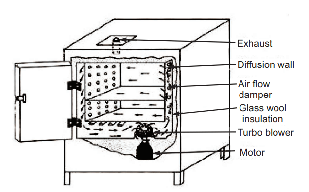
Hot air oven:
Principle: Sterilizing by dry heat is accomplished by conduction. The heat is absorbed by the outside surface of the item and then passes toward the center of the item, layer by layer. The entire item will eventually reach the temperature required for sterilization to take place. Dry heat does most of the damage by oxidizing molecules. The essential cell constituents are destroyed and the organism dies. The temperature is maintained for almost an hour to kill the most difficult of the resistant spores.
Construction: Hot air oven is consist of a double-walled chamber of aluminum or stainless steel separated from the outer case by a thick layer of insulation made up of fiberglass. Insulation is also filled in the hollow flanged door, which carries an asbestos jacket that provides a tight seal. Heating is affected by an electrical heating element and a thermostat automatically controls temperature.
Temperature and time relation for hot air oven
| Temperature( °C) | Time (h.) |
| 140 | 3 |
| 150 | 2.5 |
| 160 | 2 |
| 170 | 1 |
| 180 0.5 | 0.5 |
Diagram:
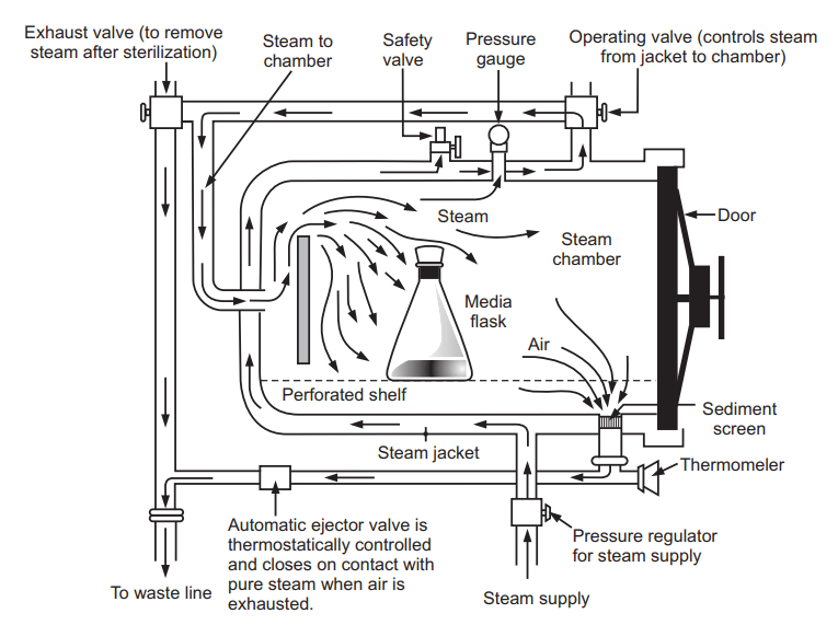
Autoclave (Moist Heat Sterilizer)
Auto claves of different sizes from 5 liters to several hundred liters capacities are available in horizontal or vertical designs.
Construction: An autoclave has a body, an internal heating system, a container to hold material, its cover fixed with a pressure gauge, a safety valve, a pressure release valve, etc. The lid is tightened with the help of screws and a gasket seals the body and lid. A jacket, paddle liger, timer, indicator, etc., are also provided with large-sized autoclaves. Autoclaves may be constructed of aluminum, mild steel, stainless steel, or gunmetal. The industrial autoclave can accommodate a large trolley containing a huge number of glassware or large bioreactors.
Principle: Moist heat destroys microorganisms by the irreversible denaturation of enzymes and structural proteins. When water boils when its vapor pressure equals that of the surrounding atmosphere. Hence in this way steam is a gas, increasing its pressure in a closed system increases its temperature. As the water molecules in steam become more energized, their penetration increases substantially. Saturated steam has greater penetration power. When steam comes in contact with a cooler surface it condenses to water and gives up latent heat to that surface. The condensed water ensures a moist condition for killing the microbes present. It is important to note that the sterilizing agent is the moist heat, not the pressure.
Diagram:
Temperature and time for autoclave
| Pressure (lb/sq. inch) | Temperature (°C) | Holding Time(min.) |
| 10 | 115.5 | 30 |
| 15 | 121.5 | 20 |
| 20 | 126.5 | 15 |
Procedure:
- Pack the object to be sterilized in a material that does not create any obstacle for steam penetration and removal of air. Pack the material in tubes, and bottles and close with a cotton stopper, flask plugged with cotton, or loosely applied screw cap. Wrapping cloth or plastic or Krag paper may be used for wrapping the instrument.
- Place sufficient water up to the required level in the chamber and place the material on the perforated tray just above it.
- Close the door to seal it completely. Open the manual discharge tap and start heating. Adjust the safety valve to the required pressure. The steam-air mixture is allowed to escape freely till all the air has been displaced.
- Close the discharge tap and wait till the pressure is reached the required level. When the holding period is over, turn off the heater and allowed it to cool till the pressure on the gauge is equal to atmospheric pressure. Open the discharge tap slowly and the air is allowed to enter the autoclave. Finally, open the autoclave and unload.
Precautions:
- Check the water level each time, the heating elements should remain immersed in the water.
- Check the spring of the safety valve frequently and clean the opening whenever necessary.
- The opposite screws of the lid should be tightened simultaneously.
- Do not overtighten the screws to avoid damage to the gasket
Advantages
- Microorganisms are destroyed more efficiently by steam sterilization than by dry heat sterilization because of greater penetration power.
- The method is applied to a wide variety of materials and for the large lodge.
- Spores are easily destroyed.
- Nontoxic to patient, staff, and environment.
- Cycle easy to control and monitor.
Disadvantages:
- Itis is unsuitable for the sterilization of powders and oils.
- It cannot be used for sterilization of injections and articles, such as plastics which get spoiled at 115- 116 0 C for 30 minutes.
- Cannot be used for thermolabile material.
Application
- The method is used for the sterilization of surgical dressing and surgical instruments.
- The containers and closures are sterilized by autoclaving.
- It is used for the sterilization of a majority of official injections which can withstand the pressure of 15 lbs/sq. inch for 30 minutes.
Make sure you also check our other amazing Article on: What is the radiation constant of painted glass?